Buscar este blog

Mostrando entradas con la etiqueta FLISOL. Mostrar todas las entradas

jueves, 22 de diciembre de 2011

Richard M. Stallman nos anima a salir a la calle el 15 de Octubre

Stallman es un hombre singular. Sus declaraciones no siempre son de agrado de todos. Muchas veces sus motivos están cargados de razón, otras veces sus declaraciones son sacadas fuera de contexto y muy pocas veces se equivoca. Podemos estar de acuerdo en este punto o no, pero Richard Stallman es la voz mas libre de todo el Software Libre.

Y hablando de libertad. Stallman nos anima, explicando sus razones... siguiendo el movimiento #WeAre99% - #globalchange, para salir a la calle el próximo día 15 de Octubre. Ese día esta prevista una manifestación a nivel mundial por la defensa de nuestros derechos como ciudadanos.


Todos estamos invitados a participar, a subir a la red nuestros motivos, tal como tambien nos indican en Tomalaplaza.net:

martes, 10 de mayo de 2011

Antena Parabólica para 2.4 ghz

Antena Parabólica para 2.4 ghz


Luego de haber divagado bastante con el tema de mi antena, me incliné por hacer el modelo parabólico. Esto se debe a que tuve la suerte de conseguir un disco de TV satelital de 80cm ;).  Con respecto al disco, puede ser también uno de DirectTV o de SKY (aprovechando que se tomaron el palo de nuestro benefactor país )

Lo primero que hice fue buscar qué poner el foco de la parábola como "iluminador". Luego de varias búsquedas elegí la guía de onda que era lo más fácil de hacer y a su vez daba buenos resultados.
Nota: Lo ideal para este caso sería una biquad, pero me resulto medio complicada de hacer.

La guía la hice siguiendo estas instrucciones, pero adaptándola a las medidas que de mi tarro. (tarro de aceite mazola). Las medidas para hacer la guía con el tarro de aceite mazola son:


Frecuencia
2.422 Ghz
Diametro 83mm
Lo 123,86
Lg 255,63
Lc 141,59
Lg/4 63,90
Lg3/4
191,72
Lo/4
30,96


No se en qué estaba pensando cdo elegí la freq, ya que no es la que estamos usando en nuestra red, pero buej!.. el daño ya está hecho.

Todos estos calculos estan hechos para el canal 3 cuando debieron ser para el canal 6.. oouuuch...


Luego, para proteger la guia de onda, use un caño de PVC de 10cm de diámetro con dos tapas. (foto1,foto2) .

Por dentro se ve asi (foto1,foto2)

Soporte

El soporte para sujetar la guia de onda, se lo hice con una moldura de aluminio que secuestré de una heladera vieja que había en mi casa!  ;) y el fleje central de un patin lecsese viejo 8) . Es importante lograr algún diseño que nos permita luego ajustar la antena con cierta precisión y que permanezca en su lugar pese al viento y la lluvia.


Finalizando

Una vez colocado el tarro en el soporte de la parábola, estaría lista para apuntarla.


Nótese la inclinación que lleva, esto es así porque el foco en esta parábola no se ecuentra en el centro, sino mas hacia abajo. Otro dato a tener en cuenta es que ésta antena (en la foto) está apuntada a un cerro que mide 1000mts desde el suelo. Si tuviesemos que apuntar a un lugar más nivelado, debería estar mas inclinada hacia abajo aún.

Cualquier duda que tengas sobre los conceptos volcados en ésta page consultame a <lu7mra at qsl.net> , para todo lo demás existe Gooooooogle  ;).

nota completa 

A small TV aerial (UDA(*) YAGI)


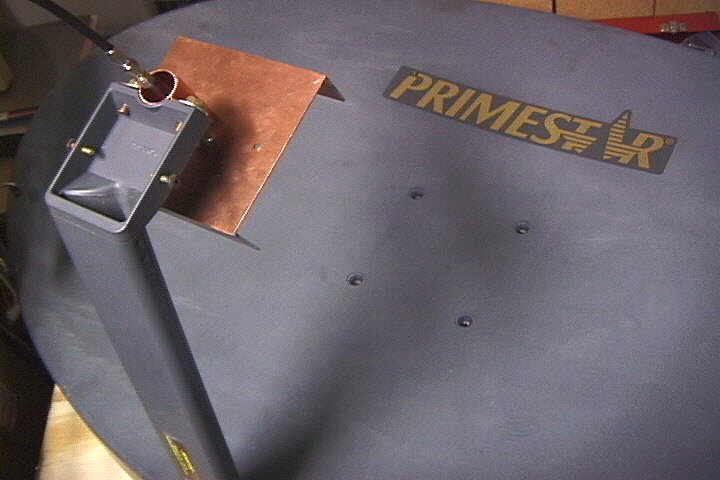
Looks like a Barbie (tm) TV aerial, but it seems to work.
http://users.skynet.be/chricat/antennes/yagi8s.jpg hi http://users.skynet.be/chricat/antennes/yagi8p.jpg http://users.skynet.be/chricat/antennes/yagi8p2.jpg
It is based on calculations from the Java applet on http://fermi.la.asu.edu/w9cf/yagipub/index.html . I started from one of the examples (70 cm, 12 elem) and scaled it to 2400 MHz as explained. I used 1.5 mm² domestic wire. I drilled small holes in the wood to put the wires in and I glued them in. One can see pieces of matches glued to fix the 'N' connector. I just used 8 elements for a first test because my wooden stick wasn't any longer...
I am not sure whether it is a good idea to use wood, wires, folded dipole, etc... (the antenna should be adapted to the coax ?300 Ohms - 50 Ohms, ?balun) But the idea is worth a try. I just tested it in my apartment and it seems to be as good as a tin can or a BiQuad. ( http://www.saunalahti.fi/~elepal/antenna2.html, http://trevormarshall.com/biquad.htm, http://www.saunalahti.fi/elepal/antenna4.html, http://martybugs.net/wireless/biquad/).
I made two longer ones (66.5 cm, 20 elements). One with domestic electrical tubing (gray) that does not work and another one with a wooden stick (7x7 mm²) that gives me three dB's more (I expected five). Maybe, it is because the wood is thicker? I don't know yet what is important and what is not. What would make a good boom? Is it reproductible?... At first sight, it is easy to build, cheap and gives many dB's.
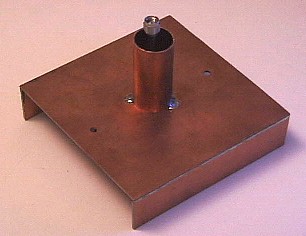
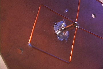
Branislav M. asked me how I did wire the dipole on the 'N-Connector'. Well, it is probably not the way to do... (I should use a Ballun, do it more carefuly,...). But it is the way I did it. And it seems to work (at least with a 2.5 meters pigtail). I have no idea how better it would be if it was 'well' done.
http://users.skynet.be/chricat/antennes/folded-dipole-z.jpg
The 20 elements has been tested on 9.5 km (with a CardboardHorn on the other side) (Liege20020615) :
Here is the comparison with other antennae :
http://users.skynet.be/chricat/horn/retinne.png
Beware of polarization!. It matches a parallel Marconi (Lambda/4 piece of copper)(all antenna wires in the same plane). Horizontal ones would go well with vertical Slotted Wave Guides (http://trevormarshall.com/waveguides.htm)
http://users.skynet.be/chricat/antennes/L4.jpg
The original page is on http://ReseauCitoyen.be/?UdaYagi (sorry, it is in french, but there are other DIY antennas on http://ReseauCitoyen.be/?HomeMade and some experiments on http://ReseauCitoyen.be/?LongShots ; note that we use hierarchical lines to ease the navigation within our wiki (something like >Hardware>Antennas>Yagi) ).
Elem    length     distance (mm)
 1       61           0       (reflector)
 2       60           19      <- driven elem, it is a 'folded dipole'...
 3       56           26
 4       55           40
 5       53           60
 6       53           84
 7       52           112
 8       52           144
 (9      51           178)   (my stick is shorter,
 (10     51           215)       for a first test, it is good enough)
 (11     51           255)
 (12     50           296)
NB: I don't know where to link it on this wiki. If somebody can help. Thanks! (photos are still in Belgium; a local copy would be welcome)
  • -- xof, Liege, Belgium

See also :
This one is based on the Frisko design :
http://users.skynet.be/chricat/antennes/Frisco2.jpg
Elem    length     distance (mm)
 1       58           0       (reflector)
 2       53.5         20      <- driven elem, it is a 'folded dipole'...
 3       52           35
 4       51.5         50
The wire is 0.8 mm brass (model-making)

During the Belgian Microwave Roundtable 2002, I got the opportunity to 'measure' it (with a Network Analyser, thanks ON4AOD). The S11/SWR plot is on http://users.skynet.be/chricat/antennes/UdaYagi-swr-300h.png. (But don't ask me what it exactly means for the moment. It seems it is not so bad somewhere in the ISM band...;-)

Another crazy idea is to use Tetra Brik (Milk or Juice carton) as a wave guide antenna. It contains enough aluminium to reflect waves. See http://ReseauCitoyen.be/?BoiteDeLait . It is also easy to add a horn and get more dB's. :-)
http://users.skynet.be/chricat/antennes/JusDeFruit.jpg http://users.skynet.be/chricat/antennes/JusDeFruit2.jpg
Lg = 1 / SQRT(1/(L0*L0) - 1/(Lc*Lc))
and Lc = 2 * width
width is here 9.5 cm -> Lg is ~16.6 cm at L0=12.5 cm (2400 MHz); The rod is thus at ~4 cm from the bottom of the brick. The rod is Lambda/4, about 3 cm. It is 'fragile', but so easy to build... (and you can already go far away, probably more than 2 km with two of them).
For further adventures with horns, see CardboardHorn
07sep2002, another Tetra Brik horn was used with a SlottedWaveguide (this one) on a ~15 kilometers link in Belgium (Louvain-La-Neuve -- Waterloo). The bigger CardboardHorn (see the picture) allowed 300 KB/sec.
http://bh.udev.org/filez/photos/lln-waterloo/640/acj.640.jpg

For the skeptics, I just ran some tests. I compared my antennae about 30 meters away from a (vertical) Lambda/4 inside my apartement (it goes through a window and there are a few tree leaves in the path, so don't extrapolate the distance).
http://users.skynet.be/chricat/antennes/comparison.png
Ups and downs show the polarization effect (vertical/horizontal). This (short) Uda-Yagi is the best :-). Of course, a longer one will still be better.
Measurement are done with the iwspy of the wireless tools on Linux (http://www.hpl.hp.com/personal/Jean_Tourrilhes/Linux/Tools.html and plotted with http://www.gnuplot.info/). I also use a front-end (http://ReseauCitoyen.be/scripts/dynspy-0.07.txt (a perl script, rename -> .pl) found on http://ReseauCitoyen.be/?TestTools to log the measurements and see the dynamics.

*Note: The Yagi-Uda provides an object lesson in the importance of good communication skills. This antenna was invented in the early part of the 20th century by a pair of Japanese engineers named Uda and Yagi. Uda san was the brains of the operation and had the key idea, but had very limited english. Yagi, however, was fluent enough in english to take care of the publication. As you've seen, he has been immortalized (at least among radio weenies), while Uda languishes in obscurity.) (ref)
NOTA COMPLETA

lunes, 9 de mayo de 2011

Construcción de una antena direccional Loop Uda Yagi para wifi - 2.4 Ghz.


Por Inco
Fotos : Kokoloko
0001 
pelando el cable 0002 enrollando anillas en 35mm 0003 
marcando anillas 0004 
cortando anillas 0005 muchas 
anillas
0001 pelando el ... 0002 enrollando ... 0003 marcando an... 0004 cortando an... 0005 muchas anil...
0006 varios 0007 
cortando tubos 0008 mesa y 
tubos 0009 
haciendo marcas 0010 
pinza para anillas
0006 varios.jpg 0007 cortando tu... 0008 mesa y tubo... 0009 haciendo ma... 0010 pinza para ...
0011 primera anilla preparada 0012 la 
segunda 0013 
soldando la sexta 0014 soldando 0015 otro 
soldando
0011 primera ani... 0012 la segunda.jpg 0013 soldando la... 0014 soldando.jpg 0015 otro soldan...
0015 
va tomando  forma 0016 
reflector 0101 0102 0103
0015 va tomando ... 0016 reflector.jpg 0101.jpg 0102.jpg 0103.jpg
0104 0105 0106 0107 0108
0104.jpg 0105.jpg 0106.jpg 0107.jpg 0108.jpg
0109 soporte loop soporte loop2 soporte y 
reflector
0109.jpg soporte loop.jpg soporte loop2.jpg soporte y reflec...
El diseño de esta antena yagi se basa en otros encontrados en internet y sobre todo en los datos obtenidos con el programa de G6KSN loopyagi.exe antes alojado aqui y que sirve para calcular antenas loop uda yagi para cualquier frecuencia. Las dimensiones y la forma de construirla se han cambiado levemente para adaptarnos a los materiales que teníamos a nuestro alcance. Es una antena direccional y con ganancia bastante alta, 14dbi. La polarización horizontal o vertical depende únicamente de la posición en que fijes la antena.
esquema original G6KSN Figura 1: Esquema de la antena original de G6KSN
Los resultados obtenidos con loopyagi.exe para una frecuencia de 2441Mhz son los siguientes :
Elemento              Dimensiones       Distancia desde 
                                            el  reflector1

   reflector 1       123mm diametro             0 mm
   reflector 2       135mm circunferencia      42 mm
   alimentador       123mm circunferencia      55 mm
   director  1       114mm circunferencia      70 mm
   director  2       114mm circunferencia      81 mm
   director  3       114mm circunferencia     105 mm
   director  4       114mm circunferencia     129 mm
   director  5       114mm circunferencia     146 mm
   director  6       114mm circunferencia     177 mm
   director  7       114mm circunferencia     225 mm
   director  8       114mm circunferencia     273 mm
   director  9       114mm circunferencia     321 mm
   director 10       114mm circunferencia     369 mm
   director 11       114mm circunferencia     417 mm
   director 12       114mm circunferencia     465 mm
   director 13       110mm circunferencia     513 mm
   director 14       110mm circunferencia     561 mm
   director 15       110mm circunferencia     609 mm
   director 16       110mm circunferencia     657 mm
   director 17       110mm circunferencia     705 mm
   director 18       110mm circunferencia     753 mm
   director 19       110mm circunferencia     801 mm
   director 20       110mm circunferencia     849 mm
   director 21       106mm circunferencia     897 mm
   director 22       106mm circunferencia     945 mm
El mástil (pieza a la que van soldados el resto de los elementos) es un tubo de cobre, usado en fontanería, de 12mm de diámetro. Los elementos en forma de anilla están hechos a partir de un alambre de cobre de 1.5mm de diámetro.
Dependiendo de la ganancia que queramos conseguir tendremos que hacer la antena mas o menos larga, aquí damos las instrucciones para hacer una de aproximadamente 1 metro de longitud y 22 directores, que da una ganancia aproximada de 14Dbi. Si se quiere hacer una antena de menor ganancia basta con acortarla hasta donde desees, por ejemplo, una antena de 50cm y 11 directores tiene una ganancia de aproximadamente 11Dbi. Como orientación decir que en las pruebas realizadas se obtuvieron ganancias de 7db (la de 22 directores) y 4db (la de 11 directores) por encima de los resultados obtenidos con una antena tipo bote (de 8.7 cm de diámetro y 16.5cm de longitud).
Empezaremos haciendo las anillas, quitamos la funda aislante del cable de cobre, y a continuación enrollamos el alambre sobre un trozo de tubo de cobre de 35mm de diámetro, hasta hacer 12 vueltas completas. Fijamos el alambre con alguna cinta adhesiva y con una cuchilla, dando varias pasadas, hacemos una marca a todas las anillas. Soltamos la cinta, retiramos el alambre del tubo de cobre y vamos cortando cada anilla por las marcas que hemos hecho. Se manipulan las anillas hasta conseguir que formen un círculo completamente cerrado. Estas doce anillas serán los primeros alimentadores numerados del 1 al 12.
El paso anterior lo repetimos enrollado el cable sobre un tubo de 34mm de diámetro, (nosotros utilizamos un tubo de una aspiradora). Sobre este tubo hacemos ahora otras 10 espiras, las marcamos y cortamos. A dos de éstas les cortamos 4 mm, para utilizarlas como directores 21 y 22, las restantes 8 anillas serán los directores del 13 al 20.
Medimos dos trozos de alambre de cobre, uno de 123mm y otro de 135mm para hacer el Alimentador y el Reflector 2 respectivamente. Les daremos también forma circular enrollándolos sobre un tubo de 40mm de diámetro y rematando la forma a mano.
Cortamos el tubo de cobre que formará el mástil, la longitud depende del número de directores de la antena que nos propongamos hacer. Para la de 22 directores lo cortaremos a 102 cm, es decir, 7.5cm mas largo que la medida que nos indica la tabla (Director 22 945mm).
A continuación sujetamos, con alguna herramienta o cinta adhesiva, una cinta métrica al tubo de cobre y le hacemos las marcas en las que irán soldados los distintos elementos. Comenzamos haciendo una marca a 7cm de uno de los extremos. Esta marca la tomamos como origen o "cero" para le resto de las medidas, o sea, en ella irá soldado el Reflector1. A 42 mm del "cero" haremos la marca para el Reflector2, a 55 mm del "cero" haremos la marca para el Alimentador, a 70 mm del "cero" la marca para el Director1, a 81mm la del Director2 y así hasta llegar al Director22.
Ya sólo nos queda soldar cada elemento en su sitio. Empezaremos por el último director, el 22. Para esto hemos preparado una herramienta o pinza que se puede desplazar por el tubo de cobre y tiene unos brazos que permiten sujetar firmemente una arandela en su posición correcta mientras la soldamos. La soldadura la hacemos con soplete de fontanero, aplicando previamente decapante o flux en las piezas a unir. Tanto los directores, como el Reflector2 se sueldan con la abertura de la anilla en contacto con el tubo de cobre, de modo que al soldar la anilla al tubo queden también unidos los extremos de la anilla.
El Director se suelda de forma que la ranura quede diametralmente opuesta al punto de unión de la arandela al tubo. En los extremos sueltos del Alimentador soldaremos posteriormente el cable coaxial, la malla a uno de los extremos y el vivo al otro. Soldamos a continuación el Reflector 2. esquema Reflector1 El Reflector1 es un círculo de 123mm de diámetro de chapa de latón de 0.5mm de espesor. Se marca con compás o plantilla y se corta con la tijera para chapa. En este reflector hacemos dos agujeros, uno con centro a 26mm del centro del reflector, y de 12mm de diámetro, en este agujero soldaremos el mástil. Hacemos otro agujero, de 4mm de diámetro y con centro a 18mm del centro del reflector. En este agujero soldaremos un trozo de tubo de latón de 4mm de diámetro y de 60mm de longitud. Por el interior de este tubo se introduce el cable coaxial RG-316, soldamos el cable coaxial al Alimentador y en el otro extremo del cable le colocamos el conector apropiado, dependiendo a que aparato Wifi vayamos a conectar la antena.
Herramientas que necesitas:

  • Un cortatubos o un arco de sierra para metales.
  • Unas tijeras para cortar chapa.
  • Unas tenazillas para cortar los cables, la tijera de chapa puede servir.
  • Un soplete, estaño y flux.
  • Estaño y un estañador, si es de 100watios mejor que el de 40watios.
  • Un tornillo de banco para sujetar las piezas mientras las sueldas.
  • Tubos de diferentes diámetros para enrollar las anillas (35mm, 34mm, 40mm)
Donde conseguir los materiales:

  • El cable de cobre de 1.5mm de diámetro en cualquier tienda de material eléctrico.
  • El tubo de cobre de 12mm de diámetro en cualquier almacén de material de fontanería o inculso en grandes superficies dedicadas a bricolage.
  • La chapa de latón la he comprado en Suministros Azán, en el polígono de Argales en Valladolid. Cuesta unos 28 euros una plancha de 100x60cm aprox.
  • El tubo de latón de 4mm y la varilla de latón de 4mm de diámetro o similar (para hacer la pinza para sujetar las arandelas) en grandes superficies de bricolage o en tiendas dedicadas a maquetas y modelismo, como Biplano al lado de San Benito, en Valladolid.
  • El RG-316 se encuentra en amidata en Madrid, en bobinas de 25 metros.
  • El conector N macho para soldar a cable (para rg-58, no se encuentra para cable mas fino) en cualquier tienda de componentes electrónicos, en Valladolid en Oseca, en la carretera de circunvalación. También en Oseca la abrazadera para sujetar la antena a un mástil.
  • La chapa perforada para hacer el soporte de la antena se compró en AKI en el Camino Viejo de Simancas, pero puede servir cualquier otra chapa de 2mm de grosor y tamaño 7cmx15cm. 
  • NOTA COMPLETA

Trevor Marshall BiQuad 802.11b Antenna 11dBi, wide band

Trevor Marshall


BiQuad 802.11b Antenna

11dBi, wide band


Some of Trevors test equipment

***Engadget builds and tests a BiQuad/Primestar combination ***
Click here for details of Mark LaPierre's 1100ft link through forest canopy, and comparison with Pringles can performance.
Click here to link to Koen Weijand's page on using an 18inch dish and feed details
Link to my tutorial 'Antennas Enhance WLAN Security' from BYTE.com, October, 2001
Click here to read about the High Gain (15-17dBi) Slotted Waveguide WLAN antennas
Low sidelobe 802.11b BiQuad feed for Primestar dish
The Primestar dishes are high gain, low cost, parabolic reflectors with an offset feed. They have superior sidelobe performance when compared with a wire grid antenna, reducing the chance that somebody off of the axis of your link will be able to interefere with it. But they are hard to feed because the f/d ratio varies from about 0.5 in the vertical axis to 0.8 on the horizontal axis.
Additionally the spacing between the feed 'slot' and the feed mounting bar is small (about 55 mm), which is less than a half wavelength at 2.4GHz
Failure to couple efficiently to the dish's wide aperture, or to minimize radiation into the mounting bar, will result in poor gain and/or significant sidelobes.
The feed is oriented for vertical polarization in this photo. To make it horizontal merely rotate the feed by 90 degrees. You will lose about 3dB of gain when using the horizontal mode, as the biquad's radiation pattern is a better match for the dish's oblong shape when vertical polarization is used.
Primestar Dish with Biquad Feed in vertical polarization mode

Construction of the Biquad
I used Printed Circuit board scraps for the 110 x 110 mm reflector, but it will be just as effective if made out of sheet brass or copper. Aluminum can be used if soldering of the rigid coax is not required at the feed point.
The reflector's 'lips' are 30 mm high, and serve to reduce coupling into the mounting bar. Note that they are only required along the main edge axis of the reflector. The lips cut down radiation from the rear lobes of the biquad by about 6 dB
The best SWR is obtained when the biquad loop is about 15mm above the ground plane, and the SWR may be adjusted by varying this distance.
If you are making a stand-alone antenna, rather than a feed, you will get better gain from a reflector 123 x 123 mm
The front view of the feed

A piece of 3/4 inch copper piping makes a tight fit with the mount supplied on the Primestar dish
The rigid 0.141 diameter coax is soldered to the groundplane to provide physical support for the structure. If the biquad element is constructed carefully there will be no component of radiation along the axis of the coax, no current is induced into the coax outer conductor, and a balun is not needed.
An SMA connector can be seen on the end of the rigid coax used to support the biquad element
Rear, showing mounting tube

To make the element take a piece of 1.2mm bare or enamelled copper wire exactly 244 mm long. Bend it in half, and then make the bends at the halfway point on each leg (where the solder joints will be). Then bend the 4 remaining right angles so that the element sides are rectangular, and there is about a 1.5mm gap for soldering to the feed. The widths of the two quad elements will be approximately 30.5mm, from wire center to wire center.
You may use standard coax cable to connect at this point, if you do not have rigid cable available, but you will have to figure out how to support the loop physically.
The best SWR is obtained when the loop is about 15 mm above the ground plane and when the reflector is mounted about 10mm in front of the Primestar's feed bracket.
Detail of the rigid coaxial cable soldering


That's all there is to it, folks -- you now have a dish with 27-31 dBi of gain and negligable sidelobe radiation (<40dB). The beamwidth is about 4 degrees.


Biquad visualized with 4NEC2 Look at NEC2.org for information on simulating the performance of the stand-alone Biquad
BiQuad Antenna for PCS CELLULAR Radio
Need a little bit more range for your cellphone? You can make a Biquad for 1900 MHz exactly the same as the one above, but start with a 304 mm long pice of wire, fold it into 8 arms approximately 39.5 and 38.5 mm long. The ground plane needs to be a little larger, use one about 160 mm (6.2 inches) square. If you don't have a coaxial RF input jack on your cellphone you can couple the signal into its existing antenna using a single quad as a matching stub. It's not perfect, but in practice it works well. Solder an alligator clip to either of the high voltage apex (39mm from the feed) of a single 152 mm loop, and clip that to the antenna stub you are currently using. Now you can put 100 ft of coax between your phone and use a roof antenna (the BiQuad) to operate even in fringe areas.

Link to my article 'Antennas Enhance WLAN Security' in BYTE.com, October, 2001

DISCLAIMER: Any resemblance between the above views and those of my employer(s) are purely coincidental. Any resemblance between the above and my own views is non-deterministic. My existence can be challenged. The question of the existence of views in the absence of anyone to hold them is left as an exercise for the reader. The question of the existence of the reader is left as an exercise in the second order coefficient.

All information published at this website is (C)Copyright 1995-2001 Trevor Marshall.
All rights are expressly reserved. Click to email webmaster onepixel.gif - 0.2 K onepixel.gif - 0.2 K onepixel.gif - 0.2 K onepixel.gif - 0.2 K onepixel.gif - 0.2 K
 NOTA COMPLETAonepixel.gif - 0.2 K